The Ray Command
| Toolbar | custom | |
| Pull-down | ||
| Keyboard | RAY | |
The Ray command creates a line similar to a construction line except that it extends infinitely in only one direction from the first pick point. The direction of the Ray is determined by the position of the second pick point.
Command Sequence
Command: RAY
Specify start point: (pick the start point)
Specify through point: (pick a second point to determine direction)
Specify through point: (to end or pick another point)
Specify start point: (pick the start point)
Specify through point: (pick a second point to determine direction)
Specify through point:
Polylines differ from lines in that they are more complex objects. A single polyline can be composed of a number of straight-line or arc segments. Polylines can also be given line widths to make them appear solid. The illustration below shows a number of polylines to give you an idea of the flexibility of this type of line.
The Polyline Family

You may be wondering, if Polylines are so useful, why bother using ordinary lines at all? There are a number of answers to this question. The most frequently given answer is that because of their complexity, polylines use up more disk space than the equivalent line. As it is desirable to keep file sizes as small as possible, it is a good idea to use lines rather than polylines unless you have a particular requirement. You will also find, as you work with AutoCAD that lines and polylines are operationally different. Sometimes it is easier to work with polylines for certain tasks and at other times lines are best. You will quickly learn the pros and cons of these two sorts of line when you begin drawing with AutoCAD.
| Toolbar | Draw | ||
| Pull-down | |||
| Keyboard | PLINE | short-cut | PL |
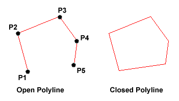
The Polyline or Pline command is similar to the line command except that the resulting object may be composed of a number of segments which form a single object. In addition to the two ends a polyline is said to have vertices (singular vertex) where intermediate line segments join. In practice the Polyline command works in the same way as the Line command allowing you to pick as many points as you like. Again, just hit  to end. As with the Line command, you also have the option to automatically close a polyline end to end. To do this, type C to use the close option instead of hitting
  . Follow the command sequence below to see how this works.
Command Sequence
Command: PLINE
Specify start point: (pick P1)
Current line-width is 0.0000
Specify next point or [Arc/Halfwidth/Length/Undo/Width]: (pick P2)
Specify next point or [Arc/Close/Halfwidth/Length/Undo/Width]: (pick P3)
Specify next point or [Arc/Close/Halfwidth/Length/Undo/Width]: (pick P4)
Specify next point or [Arc/Close/Halfwidth/Length/Undo/Width]: (pick P5)
Specify next point or [Arc/Close/Halfwidth/Length/Undo/Width]: (or C to close)
Specify start point: (pick P1)
Current line-width is 0.0000
Specify next point or [Arc/Halfwidth/Length/Undo/Width]: (pick P2)
Specify next point or [Arc/Close/Halfwidth/Length/Undo/Width]: (pick P3)
Specify next point or [Arc/Close/Halfwidth/Length/Undo/Width]: (pick P4)
Specify next point or [Arc/Close/Halfwidth/Length/Undo/Width]: (pick P5)
Specify next point or [Arc/Close/Halfwidth/Length/Undo/Width]:
 In the illustration on the right, the figure on the left was created by hitting the
It is worth while taking some time to familiarise yourself with the Polyline command as it is an extremely useful command to know. Try experimenting with options such as Arc and Width and see if you can create polylines like the ones in the illustration above. The Undo option is particularly useful. This allows you to unpick polyline vertices, one at a time so that you can easily correct mistakes.
Polylines can be edited after they are created to, for example, change their width. You can do this using the PEDIT command, from the pull-down menu.
The Rectangle Command
| Toolbar | Draw | ||
| Pull-down | |||
| Keyboard | RECTANGLE | short-cuts | REC, RECTANG |
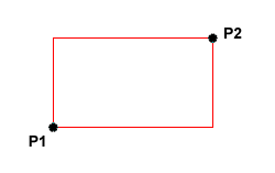
 The Rectangle command is used to draw a rectangle whose sides are vertical and horizontal. The position and size of the rectangle are defined by picking two diagonal corners. The rectangle isn't really an AutoCAD object at all. It is, in fact, just a closed polyline which is automatically drawn for you.
Command Sequence
Command: RECTANG
Specify first corner point or [Chamfer/Elevation/Fillet/Thickness/Width]: (pick P1)
Specify other corner point or [Dimensions]: (pick P2)
Specify first corner point or [Chamfer/Elevation/Fillet/Thickness/Width]: (pick P1)
Specify other corner point or [Dimensions]: (pick P2)
The Rectangle command also has a number of options. Width works in the same way as for the Polyline command. The Chamfer and Fillet options have the same effect as the Chamfer and Fillet commands, see the Modifying Objects tutorial for details. Elevation and Thickness are 3D options.
Notice that, instead of picking a second point to draw the rectangle, you have the option of entering dimensions. Say you wanted to draw a rectangle 20 drawing units long and 10 drawing units wide. The command sequence would look like this:
Command Sequence
Command: RECTANG
Specify first corner point or [Chamfer/Elevation/Fillet/Thickness/Width]: (pick a point)
Specify other corner point or [Dimensions]: D
Specify length for rectangles <0.0000>: 20
Specify width for rectangles <0.0000>: 10
Specify other corner point or [Dimensions]: (pick a point to fix the orientation)
This method provides a good alternative to using relative cartesian co-ordinates for determining length and width. See the Using Co-ordinates tutorial for more details.
| Toolbar | Draw | ||
| Pull-down | |||
| Keyboard | POLYGON | short-cut | POL |
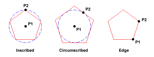
The Polygon command can be used to draw any regular polygon from 3 sides up to 1024 sides. This command requires four inputs from the user, the number of sides, a pick point for the centre of the polygon, whether you want the polygon inscribed or circumscribed and then a pick point which determines both the radius of this imaginary circle and the orientation of the polygon. The polygon command creates a closed polyline in the shape of the required polygon.
This command also allows you to define the polygon by entering the length of a side using the Edge option. You can also control the size of the polygon by entering an exact radius for the circle. Follow the command sequence below to see how this command works.
Command Sequence
Command: POLYGON
Enter number of sides <4>: 5
Specify center of polygon or [Edge]: (pick P1 or type E to define by edge length)
Enter an option [Inscribed in circle/Circumscribed about circle] <I>: (to accept the inscribed default or type C for circumscribed)
Specify radius of circle: (pick P2 or enter exact radius)
Enter number of sides <4>: 5
Specify center of polygon or [Edge]: (pick P1 or type E to define by edge length)
Enter an option [Inscribed in circle/Circumscribed about circle] <I>:
Specify radius of circle: (pick P2 or enter exact radius)

In the illustration above, the polygon on the left is inscribed (inside the circle with the polygon vertexes touching it), the one in the middle is circumscribed (outside the circle with the polyline edges tangential to it) and the one on the right is defined by the length of an edge.
No comments:
Post a Comment