Introduction
Although AutoCAD has a number of commands for creating special 3D objects, a lot can be achieved by changing the properties of basic 2D objects likepolylines. Most 2D objects can be given a thickness using the thickness option in the Properties (DDCHPROP) command. Although objects with a thickness can be said to be extruded, this should not be confused with the EXTRUDE command which creates solid extrusions; giving an object thickness produces a surface extrusion. All objects can be given an elevation by moving them in the Z direction using the MOVE command. With a combination of theMOVE and Properties commands you can quickly create simple 3D drawings.
Using this tutorial you will learn how to give objects a thickness, how to move them vertically, how to view your 3D creations and how to use the 3DFACEand SHADE commands.
The DDVPOINT Command
| Toolbar | None |
| Pull-down | |
| Keyboard | DDVPOINT |
You can use this command to get an axonometric view of your drawing.
There are a number of ways to get an axonometric view of your AutoCAD drawing but the DDVPOINT command is probably the easiest and quickest to use. It is, however, buried two layers deep in the pull-down menu so it's often quicker simply to type it at the keyboard, since there is no toolbar button. As you probably recognise from the command name it is a dialogue box driven command. The Viewpoint Presets dialogue box is illustrated on the right. As you can see, you define a view by specifying two angles. The first angle is the rotation from the X axis (the horizontal angle). The second is the angle from the XY plane (the vertical angle). Using the dialogue box you can specify an angle either by picking on the two dials or by entering an angle into each of the two angle edit boxes. You can even look at your drawing from underneath by specifying a negative vertical angle. For most purposes a horizontal angle along one of the diagonals, 45, 135, 225 and 315 and a vertical angle of 30 give the best results.
You can return to a plan view of your drawing by using the PLAN command. To do this, just enter "PLAN" at the command prompt and then  to accept the "Current UCS" default. You can also return to any previous view by using the Zoom Previous command option, Z
  P
P  at the keyboard or
  from the Standard toolbar.
The Properties Command
| Toolbar | |
| Pull-down | |
| Keyboard | DDCHPROP (single or multiple objects); DDMODIFY (single objects only) |
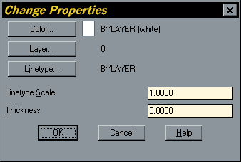
You can use the DDCHPROP command to change the colour, layer, linetype, linetype scale and thickness of any single or multiple object selection. TheDDMODIFY command gives all of these change options in addition to those which are specific to the object type. DDMODIFY is always used by AutoCAD as a default for single object selections when the Properties command is selected from the toolbar or from the pull-down menu.
Command Sequence
Command: DDCHPROP
Select objects: (pick one or more objects)
Select objects:
When you have selected the objects, the Change Properties dialogue box appears. To change the thickness, simply enter a value (in drawing units) in the Thickness edit box. When you click the "OK" button your objects will be extruded by the amount specified.
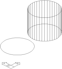
The illustration (right) shows the result of applying a thickness to a circle. A circle with no thickness is shown on the left and a circle with thickness on the right.
Effectively a circle with thickness becomes a cylinder. You can tell by the orientation of the UCS icon in this illustration that this is an axonometric view (see "The DDVPOINT Command" above for details).
Moving in the Z Direction
By now you should be quite used to using the Move command but up until now you've only been moving 2D objects in the XY Plane. Move can just as easily be used to move a drawing object vertically, perpendicular to the XY Plane. You can do this by using XY and Z co-ordinates or by picking points in 3D space.
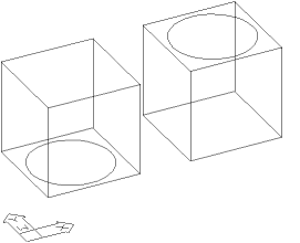 In the illustration on the left a circle has been moved from the base plane of a cube to the top face of a cube. This is done by using the MOVE command ( from the pull-down or
In the above example the move was fairly easy because we had a cube to use as a guide. Very often you will need to move an object vertically without any guide. In such a case you should use co-ordinates. For example, if the cube in the illustration above was 40 drawing units high then I could move the circle using the following command sequence.
Command Sequence
Command: MOVE
Select objects: (select the circle)
Select objects:
Base point or displacement: 0,0,0
Second point of displacement: 0,0,40
Select objects: (select the circle)
Select objects:
Base point or displacement: 0,0,0
Second point of displacement: 0,0,40
Notice that I use the UCS origin point as a base point, that's because it's standard practice but in principle it could be any point in space. The most important thing is that the X and Y co-ordinates remain the same (because we do not want to move in the XY Plane) and the Z co-ordinate must increase by the distance you want to move up. Using co-ordinate 25,43,16 as the base point and 25,43,56 as the second point would have resulted in exactly the same move. To move down you just need to specify a negative Z co-ordinate. For example to move the circle down by 40 units the second point co-ordinate would be 0,0,-40.
The 3D Face Command
| Toolbar | |
| Pull-down | |
| Keyboard | 3DFACE |
 The 3D Face command is used to draw 3D surfaces with 3 or 4 edges.
Command Sequence
Command: 3DFACE
First Point: (pick point)
Second Point: (pick point)
Third Point: (pick point)
Fourth Point: (pick point or for only 3 edges)
Third Point: (start another 3D Face or to end)
First Point: (pick point)
Second Point: (pick point)
Third Point: (pick point)
Fourth Point: (pick point or
Third Point: (start another 3D Face or
Why do I need a 3D Face?
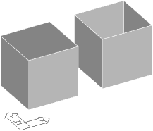
The reason is that when you give an entity like a rectangle a thickness it is given solid sides in the direction of the extrusion but it is left open ended like a tube. To add a top and a bottom to a box you must use 3D Faces. In the illustration on the right, two boxes have been shaded using the Shade command,SHADE from the keyboard, from the pull-down or  from the Render toolbar. See SHADE for a description of the Shadecommand options. The box on the right is a rectangle which has been given a thickness. As you can see, it does not have a top. A 3D Face has been added to the top of the box on the left which gives the effect of a solid surface when shaded.
When you use the Shade command, don't forget to use the Regen command to get back to the wireline drawing. AutoCAD does not allow you to pick points on a shaded drawing.
For complicated shapes you may need to use a number of 3D Faces to fill a surface. Fortunately, extruded circles are automatically given a solid top and bottom so you don't need any 3D Faces. If you do need to use a complex of faces to fill a surface there is a way to hide the join lines between faces. If you type "I" and  before the first pick point of any edge, that edge will be made invisible. If you are careful you can easily fill a complicated surface with many 3D Faces which will simply appear as a single continuous surface. If you need to create a very complex surface it may be better to use the EXTRUDEcommand which creates solid extrusions i.e. they already have top and bottom surfaces.
An Exercise
The exercise below is designed so that you can practice all of the new commands and techniques outlined above. It is a simple table which is composed of 9 main elements, 4 legs, 4 rails, and a top. These elements are all constructed using the Rectangle command, RECTANG from the keyboard or from the pull-down menu. Remember, there is nothing special about rectangles, they are just 4 sided closed polylines, so if you prefer using thePLINE command, then feel free.
These rectangles will be given a thickness using the Properties command and an elevation using the MOVE command. Some 3D Faces are used for the finishing touches using the 3DFACE command.
Drawing the Table
Step 1
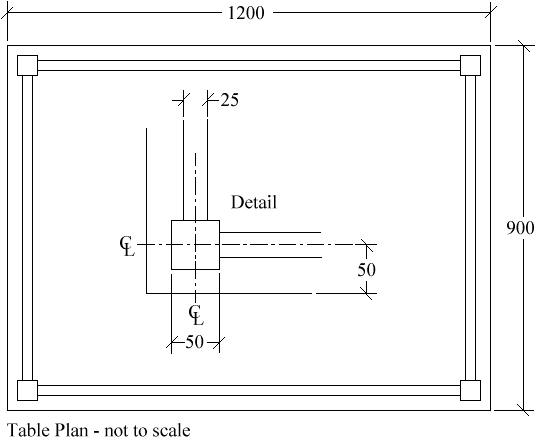
First of all draw the table plan using the dimensions on the illustration and inset detail below. All dimensions are in millimetres. The plan is composed of nine rectangles. You may need to use other commands like Line  and Offset
  to construct the rectangles. Alternatively you can work out the rectangle co-ordinates and construct them manually. Remember to use the Copy
  and/or Mirror
  commands to duplicate identical objects. For example, it's really only necessary to draw one leg since they are all the same.
Step 2
Next, using the Properties  command, select the four table legs and give them a thickness of 700. Using the Properties command a second time, select the four table rails and give them a thickness of 100. Move the rails vertically through 600 with the MOVE
  command using a co-ordinate value of0,0,0 for the base point and 0,0,600 for the second point. Finally use the Properties command a third time to give the table top a thickness of 40 and useMOVE again to give the top an elevation of 700. Now look at what you have created using the DDVPOINT command, from the pull-down or DDVPOINT at the keyboard. Use the SHADE
  command to see the solid effect, from the pull-down or SHADEat the keyboard.
Step 3
As you will have noticed, your table does not yet have a solid top. You can achieve this using 3D Face. You can start the 3D Face command from the pull-down, , from the Render toolbar,  or from the keyboard, 3DFACE. 3D Faces are defined by picking the four points of a rectangle in either a clockwise or anticlockwise direction. Start the 3D Face command and using the endpoint Osnap, select the four upper corners of the table top. Use the Shade command again to see the effect. You can use more 3D Faces to complete the model. By looking at the table from various angles you will notice that the underside of the rails, the underside of the legs and the underside of the table top all need 3D Faces in order to create a completely solid model.
Now that you have completed your model, experiment with the Shade command and the various shade edge settings (see "Tips and Tricks" below).
Step 4
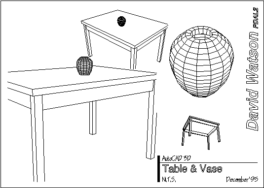
To finish your drawing, set tilemode to 0, create an A3 drawing sheet and insert some tiled viewports, see thePaper Space exercise for details. Your drawing should end up looking something like the one below. The vase was created using the REVSURF command, see REVSURF for details.
3D Objects
In addition to the simple 3D objects you can create by giving objects thickness and adding 3D Faces, AutoCAD provides a number of ready made 3D objects. These objects can be chosen from the 3D Objects dialogue box. As you can see from the illustration of the dialogue box below, you can create very simple objects like a box and complex ones like the torus.
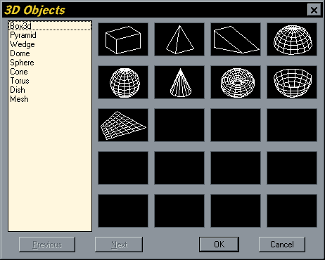
You must invoke the 3D objects dialogue box from the pull-down menu, as there is no keyboard equivalent. Alternatively you can select individual 3D Object commands from the Surfaces toolbar. Each 3D Object requires different input from the user but the command line is quite explicit so you shouldn't have any problems.
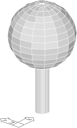 One of the most useful objects is the Sphere. In the illustration on the right a 3D tree has been created using a circle with thickness as the trunk and a sphere as the canopy. One thing to bear in mind when creating spheres is that the centre of the sphere will be on the ground plane. Therefore, half of the sphere is below ground level and half above. If you want the sphere to sit on the ground plane, all you have to do is move it up through a distance which is the same as it's radius.
Another consideration when creating spheres and some of the other shapes is the number of segments to use. It is very tempting to use a lot and create a smooth shape but this does take lots of drawing memory so go carefully. The default value (16) is usually adequate for most purposes.
Command Sequence
Invoke the dialogue box from the pull-down (), pick the sphere icon and then the "OK" button or pick  from the Surfaces toolbar.
Center of sphere: (pick point)
Diameter/<radius>: (pick point or enter value)
Number of longitudinal segments<16>: (enter number or )
)
Number of latitudinal segments<16>: (enter number or )
)
Your Sphere is drawn.
Diameter/<radius>: (pick point or enter value)
Number of longitudinal segments<16>: (enter number or
Number of latitudinal segments<16>: (enter number or
Your Sphere is drawn.
Tips & Tricks
- If you would like to try creating the vase as shown in the table drawing. You will need to know a little bit about UCS, User Co-ordinate Systems (seeUCS) and how the Revolved Surface command works (see the 3D Tree exercise for details).
- You can change the shaded effect that the Shade command gives to your drawing using the SHADEDGE variable. To change the shade edge variable just enter SHADEDGE at the keyboard and enter a value between 0 and 3.
SHADEDGE = 0 gives a shaded colour surface with no lines.
SHADEDGE = 1 gives a shaded colour surface with lines. This tends to give the best overall results.
SHADEDGE = 2 gives a background colour surface which gives a similar effect to the Hide command.
SHADEDGE = 3 gives a block colour surface, this is the AutoCAD default. See SHADE for a fuller description of the SHADEDGE variable. - Always use Osnaps when picking in 3D.
- Use the Shade command regularly to keep track of your drawing. In wireline it's impossible to tell if a surface has a 3D Face or not, so you'll need to use Shade to check.
- You can force invisible 3D Face edges to display in wireline using the SPLFRAME variable. If SPLFRAME = 0 all invisible edges remain hidden. If it is set to 1 invisible edges will be displayed. This can be extremely useful because it is impossible to select a 3D Face which has no visible edges. The only way to select such a 3D Face is to set SPLFRAME to 1 first.
No comments:
Post a Comment