Introduction
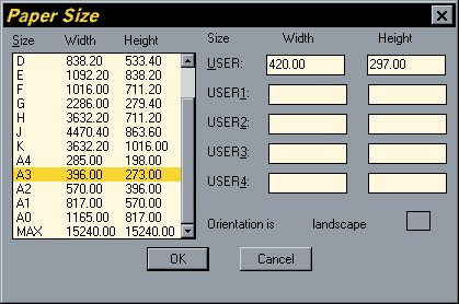
There has alwas been some confusion over the size of standard ISO drawing sheets with AutoCAD.The stated sizes in the plot dialogue box are not the true ISO sizes, rather they relate to the plotted area on standard size cut sheets. Obviously it is not possible to print right to the edge of cut sheets, so the AutoCAD sizes quoted are always smaller than the true cut sheet size. See the "Paper Size" dialogue box on the right.

 To some extent this issue has been physically resolved by the use of roll feed plotters. For example, a true A3 print can be made from an A1 roll. Despite this fact, AutoCAD still quotes the plotted area sizes in the plot dialogue box. If you look at the dialogue box above, you will see that it is possible to enter your own "USER" paper sizes which can be set as true ISO sizes. In this example the "USER" size has been set to A3. Use the sizes in the table below, which are the true ISO cut sheet sizes as a guide.
| Paper sizes in millimetres | |||
|---|---|---|---|
| A0 | 1189 | x | 841 |
| A1 | 841 | x | 594 |
| A2 | 594 | x | 420 |
| A3 | 420 | x | 297 |
| A4 | 297 | x | 210 |
| A5 | 210 | x | 148 |
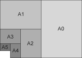
The ISO paper sizes are devised in such a way that each smaller size is exactly half the size of the previous one. For example, cutting an A3 sheet in half so that the cut is perpendicular to the longest side would result in two A4 sheets. See the illustration above.
Drawing ISO Sheets in AutoCAD
The simplest way to draw drawing sheet outlines is to use the Rectangle command, picking the lower left hand point and then entering a relative co-ordinate for the upper right.
For example
To draw an A3 sheet:
- Start the Rectangle command, type RECTANG at the command prompt, pick "Rectangle" from the "Draw" pull-down or click on the
 button.
 - At the Chamfer/Elevation/Fillet/Thickness/Width/<First corner>: prompt, pick a point somewhere in the lower left of the drawing area.
- At the Other corner: prompt, enter a relative co-ordinate using the appropriate drawing sheet dimensions, type @420,297 and right click or
 at the keyboard.
 - Your drawing sheet outline will now be drawn at the correct size. If you cannot see all of the rectangle, use Zoom Extents to view the whole thing. You can do this by typing Z
 E
E  at the keyboard (Z is the keyboard shortcut for the Zoom command).
Drawing Scaled ISO Sheets
The drawing sheet sizes in the table above can easily be used to draw sheet outlines in Paper Space since plotting from Paper Space should always normally be at a scale of 1=1 and Paper Space drawing units should be equivalent to millimetres. However, drawing sheet outlines in Model Space is rather more complicated because you need to take into account both the intended plot scale and the drawing units (which may not be millimetres). Fortunately there is a straightforward formula which you can use to determine the actual size of your required sheet outline in drawing units.
Drawing Units per metre x Scale x Sheet Size in metres
For example
An A3 sheet at 1:200 and drawing units in millimeters can be calulated as follows:
1000 x 200 x 0.420 = 84000
1000 x 200 x 0.297 = 59400
1000 x 200 x 0.297 = 59400
An A3 sheet at 1:500 and drawing units in metres can be calculated as follows:
1 x 500 x 0.420 = 210.0
1 x 500 x 0.297 = 148.5
1 x 500 x 0.297 = 148.5
Plotting from Model Space
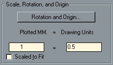
 The only other consideration you need to make when plotting in Model Space is the plotting scale. This will be different depending upon which drawing units you are using.Working in millimetres is straightforward because you can use the actual scale in the Plot dialogue box since plotted units are also in millimetres. For example, a drawing to be plotted at 1:500 with drawing units in millimetres will have a plot scale of 1=500. Working in metres is a little more complicated. You will need to divide the scale by 1000 to get the correct figure. For example, a drawing to be plotted at 1:500 with drawing units in metres will have a plot scale of 1=0.5 which is 1000 times smaller than the figure for millimetres because there are 1000 millimetres in a metre.
| Plot Scale | Plotted MM | Drawing Units | |
|---|---|---|---|
| 1:20 | 1 | = | 0.02 |
| 1:50 | 1 | = | 0.05 |
| 1:200 | 1 | = | 0.2 |
| 1:500 | 1 | = | 0.5 |
| 1:1250 | 1 | = | 1.25 |
| 1:2500 | 1 | = | 2.5 |
The table above lists a number of common plot scales and their corresponding plot scale factors which should be used when plotting from Model Space and when drawing units are in metres.
No comments:
Post a Comment