The Donut Command
| Toolbar | custom | ||
| Pull-down | |||
| Keyboard | DONUT | short-cut | DO |
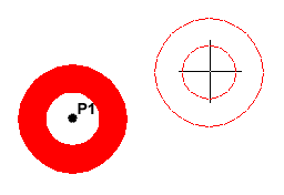
This command draws a solid donut shape, actually it's just a closed polyline consisting of two arc segments which have been given a width. AutoCAD asks you to define the inside diameter i.e. the diameter of the hole and then the outside diameter of the donut. The donut is then drawn in outline and you are asked to pick the centre point in order to position the donut. You can continue picking centre points to draw more donuts or you can hit
  to end the command. Surprisingly, donuts are constructed from single closed polylines composed of two arc segments which have been given a width. Fortunately AutoCAD works all this out for you, so all you see is a donut.
 The donut is then drawn in outline and you are asked to pick the centre point in order to position the donut. You can continue picking centre points to draw more donuts or you can hit
 Command Sequence
Command: DONUT
Specify inside diameter of donut <0.5000>: (pick any two points to define a diameter or enter the exact length)
Specify outside diameter of donut <1.0000>: (pick any two points to define a diameter or enter the exact length)
Specify center of donut or <exit>: (pick P1)
Specify center of donut or <exit>: (to end or continue to pick for more doughnuts)
Specify inside diameter of donut <0.5000>: (pick any two points to define a diameter or enter the exact length)
Specify outside diameter of donut <1.0000>: (pick any two points to define a diameter or enter the exact length)
Specify center of donut or <exit>: (pick P1)
Specify center of donut or <exit>:
As an alternative to picking two points or entering a value for the diameters, you could just hit  to accept the default value. Most AutoCAD commands that require user input have default values. They always appear in triangular brackets like this <default value>.
Curiously enough AutoCAD doesn't seem to mind if you make the inside diameter of a donut larger than the outside diameter, try it and see.
| Toolbar | Draw | |
| Pull-down | ||
| Keyboard | REVCLOUD | |
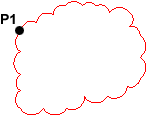
The Revcloud command is used to draw a "freehand" revision cloud or to convert any closed shape into a revision cloud.
Command Sequence
Command: REVCLOUD
Minimum arc length: 66.6377 Maximum arc length: 116.6159
Specify start point or [Arc length/Object] <Object>: (Pick P1)
Guide crosshairs along cloud path... Move the mouse to form a closed shape; the command automatically ends when a closed shape is formed.
Revision cloud finished.
Minimum arc length: 66.6377 Maximum arc length: 116.6159
Specify start point or [Arc length/Object] <Object>: (Pick P1)
Guide crosshairs along cloud path...
 Move the mouse to form a closed shape; the command automatically ends when a closed shape is formed.
Revision cloud finished.
You can use the "Arc length" option to control the scale of the revision cloud. This is achieved by specifying the minimum and maximum arc length. The "Object" option is used to transform any closed shape, such as a polyline, spline or circle into a revision cloud.
| Toolbar | custom | ||
| Pull-down | |||
| Keyboard | 3DPOLY | ||
The 3D Polyline Command
The 3D Polyline command works in exactly the same way as the Polyline command. The main difference between a normal polyline and a 3D polyline is that each vertex (pick point) of a 3D polyline can have a different value for Z (height). In normal (2D) polylines, all vertexes must have the same Z value.
3D polyline objects are not as complex as their 2D cousins. For example, they cannot contain arc segments and they cannot be given widths. However, they can be very useful for 3D modeling.
Command Sequence
Command: 3DPOLY
Specify start point of polyline: (pick a point)
Specify endpoint of line or [Undo]: (pick another point)
Specify endpoint of line or [Undo]: (pick a third point)
Specify endpoint of line or [Close/Undo]: (to end, C to close or continue picking points)
Specify start point of polyline: (pick a point)
Specify endpoint of line or [Undo]: (pick another point)
Specify endpoint of line or [Undo]: (pick a third point)
Specify endpoint of line or [Close/Undo]:
Notice that you are not prompted for a Z value each time you pick a point. You must either use one of the Object Snaps to pick a point with the required Z value or use the ".XY" filter to force AutoCAD to prompt for a Z value.
No comments:
Post a Comment